
Deutsch / English
Mit wenigen Kontakten und Bauteilen kannst Du die Fernbedienung ganz einfach selbst fertigstellen.
Super 8 Fernbedienung Bauteile anschließen – Schritt für Schritt
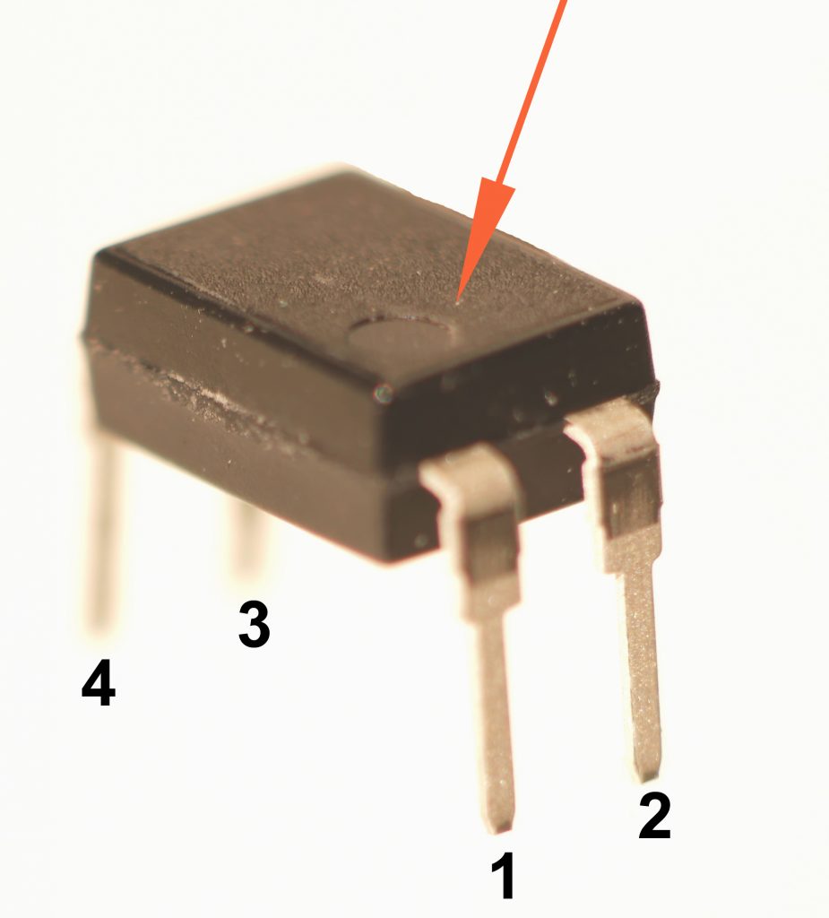
Vorab geben wir den wenigen Pins, die zu verlöten sind, ein paar Zahlen: Neben dem Board sorgt das Panasonic AQY212EH PhotoMOS-Relais für die eigentlichen Schaltungen.
Es ist ein kleines Bauteil, dessen Pins sind sehr fein sind und entsprechend nah nebeneinander liegen, daher lohnt es sich, eine feine Lötspitze zu verwenden und Female-to-Female Jumper Wire/Kabel zu verwenden, um nicht an den Pins des Boards löten zu müssen und Kurzschlüsse zu vermeiden. Unterstützend könnte es sein, wenn man den PhotoMOS mit den Pins in einer Lochplatine positioniert – ebenso könnte man auch mit dem Board und anderen Bauteilen verfahren.
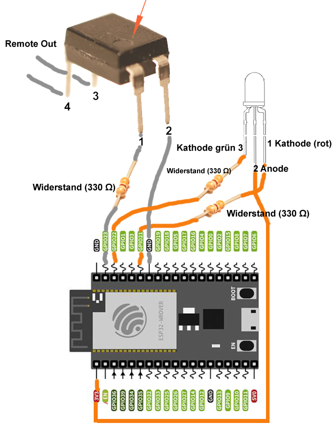
Wenn man von oben auf den PhotoMOS blickt und die Aufschrift gerade zu lesen ist, kann man in der unteren linken Ecke einen Punkt erkennen. Dem Pin unter diesem Punkt geben wir die Zahl 1. Dann numerieren wir weiter gegen den Uhrzeigersinn: Unten rechts Pin 2, oben rechts Pin 3 und oben links Pin 4.
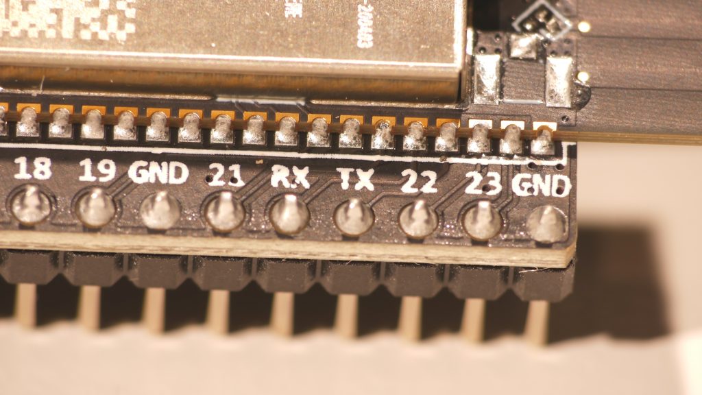
Verbinde jetzt mit einer Kabellitze und einem Widerstand (330 Ω) Pin 1 mit Pin 23 am ESP32-DevKitC-VE-Board und Pin 2 des PhotoMOS mit einem beliebigen Erdungs-Pin (GND).
Auch für die Verbindungen am Board sind Crimpkontakte 2,54 mm (Pins) mit Buchsengehäuse 2,54 mm und/oder Female-to-Female Jumper Wire zu empfehlen.
An Pin 3 und 4 des PhotoMOS kannst Du jeweils Kabellitzen anbringen. Sie können später direkt oder via Steckverbindung mit dem Remote-Kabel, das in die Super 8-Kamera führt, verbunden werden. Für Maximale Zugentlastung empfiehlt es sich natürlich, später alles in einem kleinen Gehäuse unterzubringen, von dem aus Du eine Steckverbindung zur Kamera herstellen kannst. Du kannst also Pin 3 und 4 z.B. an eine stabile 6,3mm-Klinkenbuchse anschließen, von der aus Du dann mit einem Adapterkabel 6,3mm auf 2,5mm Deine Kamera anschließen kannst.
Schließe dann die 2-Farb-LED an. Diese LED hat 3 Pins in verschiedenen Längen. Bei der Anordnung der Pins ist auf die Herstellerangaben zu achten. Nicht immer lassen sich die Pins über die Längen zuordnen. Bei der LED, die ich noch verlinke, ist der längste Pin in der Mitte, die Anode. Diese wird am ESP32-DevKitC-VE-Board mit dem 3V3-Pin verbunden. Einfach mit einer Litze, ohne Widerstand.
Die Kathode (rot) ist der zweitlängste Pin an der LED. Diese wird mit einem Widerstand (330 Ω) mit Pin 21 am ESP32-DevKitC-VE-Board verbunden. Bei der LED hier ist der kürzeste Pin die Kathode (grün). Diese wird mit einem Widerstand (330 Ω) am Board mit dem Pin 22 verbunden.
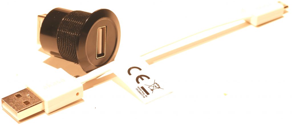
Für den Feld-Einsatz und grundsätzlich für höhere Stabilität kann die Micro-USB-Buchse am Board z.B. durch eine Einbau-USB-A-Buchse entlastet werden. Am einfachsten verbindest Du sie mit einem kurzen Adapterkabel USB A auf Micro USB in Deinem Gehäuse mit dem Board. Es gibt auch preisgünstigere Varianten, wenn man USB löten möchte.
Über die Buchse kann die Remote dann via Powerbank oder Netzkabel (z.B. Handy-Ladekabel) betrieben werden. (Ich werde bei Gelegenheit auch noch den Anschluss für 4 AA-Batterien beschreiben. Hierbei wäre jedoch noch ein zusätzlicher On/Off-Schalter und eine Sicherung zu empfehlen – und das USB-Kabel müsste, wenn man ganz sicher sein will, auch noch mit einem Wechselschalter versehen werden…).
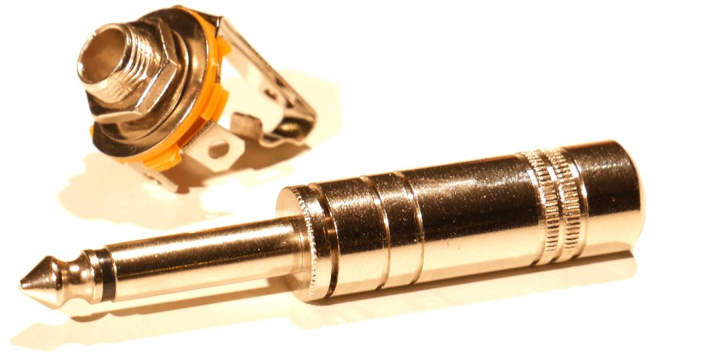
Für den Remote Ausgang habe ich mich aus Stabilitätsgründen auch für die weitaus robustere 6,3mm-Einbau-Klinkenbuchse, (statt 2,5mm, wie an der Kamera), entschieden. Man hat hier mehrere Optionen: Man könnte z.B. an Pin 3 und 4 am PhotoMOS auch direkt ein längeres 2-litziges Kabel anschließen, das am anderen Ende einen 2,5mm-Klinkenanschluss bereithält und damit direkt in die Kamera gehen. Nachteil ist hierbei, dass man unflexibel ist und immer ein Kabel an der Box hängt.
I.d.R. sollte beim Klinkenstecker/buchse Pin 3 des PhotoMOS am Tip, also der Spitze des Steckers anliegen und Pin 4 des PhotoMOS an sleeve/Masse.
Am besten im Run-Modus testen. Sollte die Kamera nicht „anspringen“, können die Litzen von Pin 3 und 4 des PhotoMOS an den Lötfahnen der Klinkenbuchse getauscht werden. Bevor man lötet, können die beiden Litzen auch einfach drangehalten und ggf. getauscht werden.
Um das Kabel und die Kamera selbst zu testen, ist es zu empfehlen, bevor Du etwas festlötest, die Litzen des Remote-Kabels zusammen zu halten, um den Kontakt/Kurzschluss zu erzeugen, so, wie es die klassischen manuellen Fernbedienungen prinzipiel gemacht haben. So kannst Du zunächst sicherstellen, dass Kabel und Kamera tun, was sie sollten.
Connecting components to the ESP32 board
English / Deutsch
With just a few contacts and components, you can easily complete the remote control yourself.
First, let’s assign numbers to the few pins that need to be soldered: Besides the board, the Panasonic AQY212EH PhotoMOS relay handles the actual circuitry. It is a small component whose pins are very fine and therefore located close together; thus, it is worthwhile to use a fine soldering tip and female-to-female jumper wire/cable to avoid soldering on the board pins and preventing short circuits. It might be helpful to position the PhotoMOS with its pins facing out on a breadboard – the same could be done with the board and other components. Looking at the PhotoMOS from above, with the markings facing upwards, you’ll see a dot in the lower left corner. We’ll assign the number 1 to the pin below this dot. Then we’ll number them counter-clockwise: bottom right pin 2, top right pin 3, and top left pin 4.
Now, using a stranded wire and a 330 Ω resistor, connect pin 1 to pin 23 on the ESP32-DevKitC-VE board and pin 2 of the PhotoMOS to any ground (GND) pin.
Crimp contacts (pins) with 2.54 mm socket housing and/or female-to-female jumper wire are also recommended for connections on the board.
You can attach stranded wires to pins 3 and 4 of the PhotoMOS. These can later be connected directly or via a connector to the remote cable that leads to the Super 8 camera. For maximum strain relief, it’s recommended to house everything in a small enclosure from which you can connect to the camera. For example, you can connect pins 3 and 4 to a sturdy 6.3 mm jack socket, from which you can then connect your camera using a 6.3 mm to 2.5 mm adapter cable. Next, connect the dual-color LED. This LED has three pins of varying lengths. Refer to the manufacturer’s instructions for pin assignment. The pins can’t always be identified by their length. For the LED I’ll link to, the longest pin in the middle is the anode. This is connected to the 3.3V pin on the ESP32-DevKitC-VE board. Simply use a wire, without a resistor. The cathode (red) is the second longest pin on the LED. This is connected to pin 21 on the ESP32-DevKitC-VE board with a 330Ω resistor. For the LED shown here, the shortest pin is the cathode (green). This is connected to pin 22 on the board with a 330Ω resistor.
For field use and generally for greater stability, the micro-USB port on the board can be replaced with a built-in USB-A port. The easiest way to do this is to connect it to the board inside your enclosure using a short USB-A to micro-USB adapter cable. There are also more affordable options available if you prefer soldering USB connections. The remote can then be powered via the port using a power bank or a power cable (e.g., a mobile phone charger). (I will also describe the connection for 4 AA batteries at a later time. However, an additional on/off switch and a fuse are recommended for this option – and for added safety, the USB cable should also be equipped with a toggle switch…).
For the remote output, I opted for the far more robust 6.3mm panel-mount jack socket (instead of the 2.5mm socket used on the camera) for stability reasons. There are several options here: For example, you could connect a longer, two-wire cable directly to pins 3 and 4 of the PhotoMOS, with a 2.5mm jack connector at the other end, and connect it directly to the camera. The disadvantage here is that you’re inflexible and a cable is always attached to the box. Generally, pin 3 of the PhotoMOS should be connected to the tip of the jack plug/socket, and pin 4 should be connected to the sleeve/ground. It’s best to test in run mode. If the camera doesn’t „start,“ the wires from pins 3 and 4 of the PhotoMOS can be swapped at the solder lugs of the jack socket. Before soldering, you can simply hold the two wires against the jack and swap them if necessary. Generally, pin 3 of the PhotoMOS should be connected to the tip of the plug, and pin 4 to the sleeve/ground. To test the cable and the camera itself, it’s recommended that before soldering anything, you hold the strands of the remote cable together to create a contact/short circuit, just as classic manual remote controls did. This way, you can first ensure that the cable and camera are functioning as intended.
