
Deutsch / English
Die Wahl der Bauteile ist entscheidend für präzise Filmaufnahmen. Gerade bei Zeitraffer- oder Stop-Motion-Projekten mit Super-8 Kameras kommt es auf zuverlässige Impulse und stabile Signalsteuerung an.
Alle Bauteile sind im gut sortierten Elektronik-Fachhandel (auch online) zu günstigen Preisen erhältlich. Z.B. Conrad.
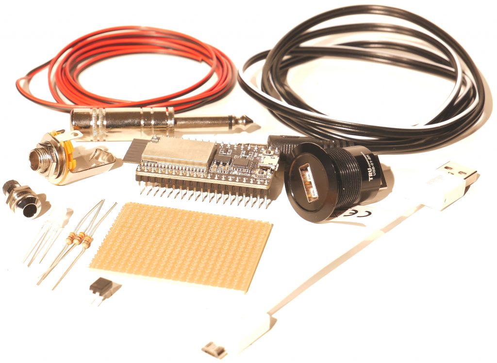
Mit wenigen Bauteilen und einfachen Handgriffen kommst Du schnell und preiswert zu einer präzisen und mulifunktionellen Fernbedienung für Deine Super8 Filmkamera:
ESP32 DevKit
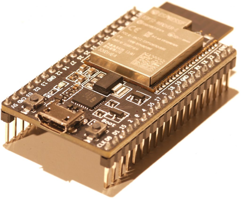
Der ESP32 ist ein Mikrocontroller mit WLAN. Er erzeugt ein eigenes WLAN (Access Point) und stellt eine kleine Webseite bereit. Dein Handy verbindet sich direkt mit dem Gerät, und Du steuerst Start/Stop, Tap und Intervalle im Browser. Vorteil: keine App, keine Installation, kein Internet nötig
Arduino IDE installieren (2.x ist ok).
Boards Manager URL hinzufügen:https://espressif.github.io/arduino-esp32/package_esp32_index.json
Boards Manager → “esp32 by Espressif Systems” installieren.
Board auswählen: meist “ESP32 Dev Module” (oder “ESP32-DevKitC-VE”, falls vorhanden).
Port wählen (COM-Port).
Sketch öffnen → Upload.
Serial Monitor: 115200 Baud → du siehst AP SSID: und AP IP:.
PhotoMOS-Relais (der „kontaktlose Schalter“ für die Kamera)
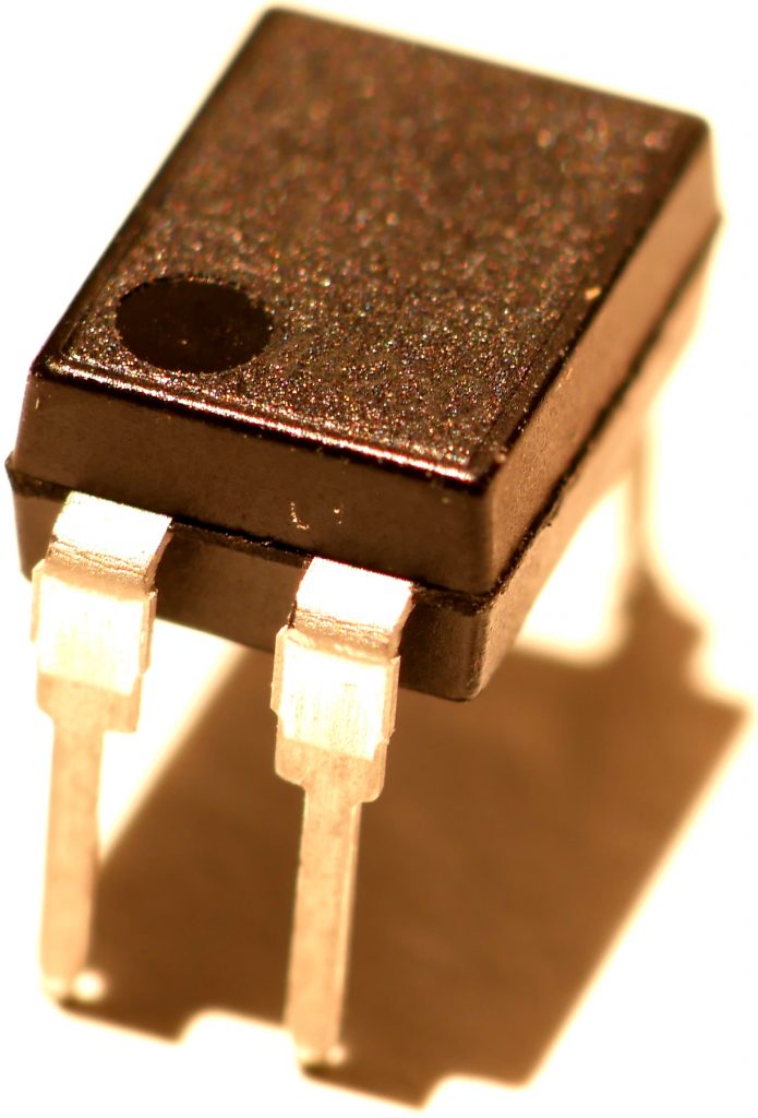
Das PhotoMOS ist ein elektronischer Schalter, der den Kamera-Auslösekontakt galvanisch getrennt schließen kann – ohne mechanische Relais-Klicks und ohne Verschleiß. Dadurch ist es sehr gut für häufiges Schalten (Timelapse/Intervalle) geeignet und schützt die Kameraelektronik vor direkten Strömen vom Controller.
Es hat sehr feine Pins. Eine Lochplatine kann beim Löten hilfreich sein.
Trigger-Ausgang (Klinke / Remote-Buchse)
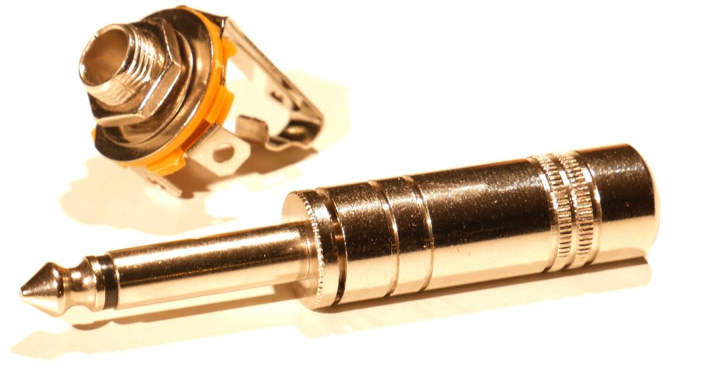
Deine Kamera wird normalerweise über einen Klinkenstecker ausgelöst: Der Remote-Auslöser schließt schlicht zwei Kontakte. Genau das macht die SMART8 Remote: Es schließt den Kontakt über das PhotoMOS. Je nach Buchse/Adapter können Tip/Sleeve/Schaltkontakt unterschiedlich belegt sein – deshalb immer einmal prüfen/ testen.
Widerstände
LED-Vorwiderstände (z. B. 330 Ω): begrenzen den Strom durch die LED, damit sie nicht durchbrennt und der ESP32-Pin nicht überlastet wird. Du brauchst sie 2x für die Rot/Grün-LED und 1x für den PhotoMOS.
2-Farb-LED (Status/Diagnose)
Die Bi-Color-LED ist eine „Indikator“ ohne Messgeräte:
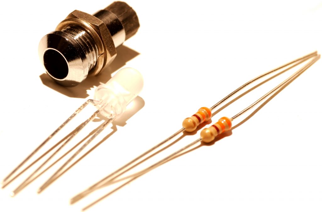
- Grün = idle/ready
- Rot = Trigger aktiv (Kontakt geschlossen)
Die Status-LED zeigt den Schaltzustand der Remote (Trigger), nicht den Zustand der Kamera.
USB-Panelbuchse + Adapterkabel (robuste Stromzufuhr)
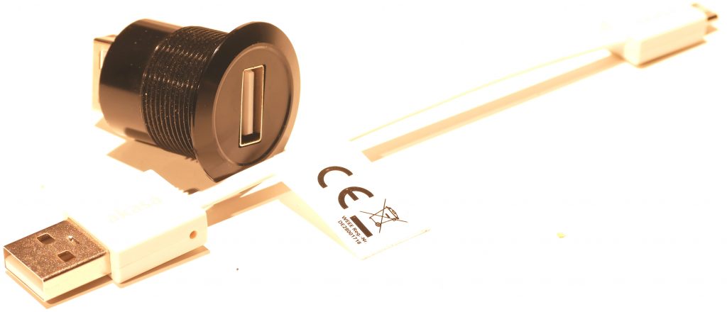
Statt das USB-Kabel einer Powerbank später direkt an das Board anzustecken (mechanisch empfindlich), nutzt du eine stabile Einbaubuchse im Gehäuse. Von dort geht ein kurzes Adapterkabel zum ESP32. Das erhöht Lebensdauer und Outdoor-Tauglichkeit. Natürlich ist das bereits Optional, aber ich empfehle eine Micro USB-Buchse nicht für einen Dauereinsatz.
Eine Beschreibung für den Anschluss von 4 AA-Batterien ist in Arbeit, ist jedoch mit mehr Aufwand verbunden: das Gehäuse müsste entsprechend größer entwickelt werden, Schalter und Sicherung sind empfohlen. Vorteil ist lediglich, dass die Stromversorgung in einem Geratät stattfindet und keine Powerbank benötigt wird.
Lochrasterplatine / Verteilerpunkt (Ordnung & Zugentlastung)
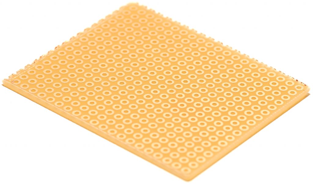
Eine kleine Lochrasterplatine eignet sich als „Verteiler“: Du kannst dort Kabel sauber anlöten, Widerstände unterbringen und alles mechanisch stabilisieren, ohne direkt am ESP32-Board herumzulöten. Das macht die ganze Verarbeitung, Wartung/Modding leichter und reduziert Kabelbruch.
Hier lesen, wie Bauteile angeschlossen werden.
(Optional) Sicherung / Batterie
Für einen Batteriebetrieb ist eine Sicherung als Schutz bei Kurzschluss/Fehlverdrahtung sinnvoll. Bei reiner Powerbank-USB-Versorgung ist der Schutz meist schon in Powerbank/Kabel/USB-Quelle integriert — trotzdem ist saubere Verdrahtung das NonPlusUltra. Diese Option werde ich bei Gelegenheit und stärkerer Nachfrage später noch ausarbeiten.
Components of the smart8 remote
English / Deutsch
The choice of components is crucial for precise film recordings. Especially in time-lapse or stop-motion projects with Super 8 cameras, reliable impulses and stable signal control are essential.
All components are available at reasonable prices from well-stocked electronics retailers (including online). For example, Conrad.
With just a few components and simple steps, you can quickly and inexpensively create a precise and multifunctional remote control for your Super 8 film camera:
ESP32 DevKit
The ESP32 is a microcontroller with built-in Wi-Fi. It creates its own Wi-Fi network (access point) and hosts a small webpage. Your phone connects directly to the device, and you control start/stop, taps, and intervals in your browser. Advantages: no app, no installation, and no internet connection required.
Install the Arduino IDE (version 2.x is fine).
Add the Boards Manager URL: https://espressif.github.io/arduino-esp32/package_esp32_index.json Install Boards Manager → “esp32 by Espressif Systems”.
Select the board: usually “ESP32 Dev Module” (or “ESP32-DevKitC-VE”, if available).
Select the port (COM port).
Open the sketch → Upload.
Serial Monitor: 115200 baud → you will see the AP SSID and AP IP address.
PhotoMOS relay (the „contactless switch“ for the camera)
The PhotoMOS is an electronic switch that can close the camera’s shutter release contact with galvanic isolation – without mechanical relay clicks and without wear. This makes it ideal for frequent switching (timelapse/intervals) and protects the camera electronics from direct currents from the controller. It has very fine pins. A perforated circuit board can be helpful during soldering.
Trigger output (jack / remote socket)
Your camera is normally triggered via a jack plug: The remote trigger simply closes two contacts. The SMART8 Remote does exactly that: It closes the contact via the PhotoMOS. Depending on the socket/adapter, the tip/sleeve/switching contact may be wired differently – therefore always check/test beforehand.
Resistors
LED series resistors (e.g., 330 Ω): limit the current through the LED to prevent it from burning out and to avoid overloading the ESP32 pin. You need two for the red/green LED and one for the PhotoMOS.
2-color LED (status/diagnostics)
The bi-color LED is an indicator without any measuring devices:
Green = idle/ready
Red = trigger active (contact closed)
The status LED shows the switching state of the remote (trigger), not the state of the camera.
USB panel socket + adapter cable (robust power supply)
Instead of connecting a power bank’s USB cable directly to the board (which is mechanically fragile), you use a robust, panel-mount socket in the enclosure. A short adapter cable then connects the socket to the ESP32. This increases lifespan and suitability for outdoor use. Of course, this is optional, but I don’t recommend a micro USB socket for continuous use. Instructions for connecting four AA batteries are in development, but this involves more work: the enclosure would need to be made larger, and a switch and fuse are recommended. The only advantage is that the power supply is integrated into a single device, eliminating the need for a separate power bank.
Perforated circuit board / distribution point (organization & strain relief)
A small perforated circuit board is ideal as a „distributor“: You can neatly solder cables, mount resistors, and mechanically stabilize everything without soldering directly to the ESP32 board. This makes the entire process of working, maintaining, and modding easier and reduces cable breakage.
Read here how to conect the components.
(Optional) Fuse / Battery
For battery operation, a fuse is advisable as protection against short circuits or incorrect wiring. With a power bank-USB connection, protection is usually already integrated into the power bank/cable/USB source—however, proper wiring is still paramount. I will elaborate on this option later if there is sufficient demand.